Skip to content

XLDsl

Dilution Refrigerator Measurement System

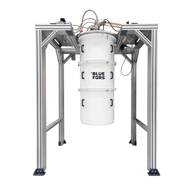
The XLDsl Dilution Refrigerator Measurement System is designed for demanding experiments that require large experimental space, extensive wiring, and superior performance.

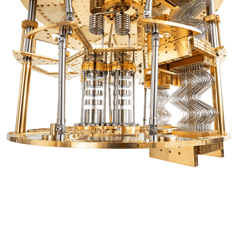
The XLDsl accommodates up to 1008 factory-installed semi-rigid 18 GHz coaxial lines in a configuration with two pulse tubes. Its side-loading feature allows experimental wiring to be prepared away from the cryostat while the system is running.

Even with its extensive capabilities and superior performance, a fully automated cool-down sequence from room to base temperature can still be carried out at the push of a single button.
Product Highlights


1.0

XLDsl

Dilution Refrigerator Measurement System


Side-Loading Enables the Fast Exchange of Wiring

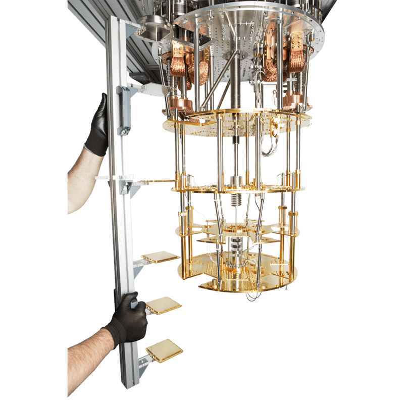
The side-loading feature allows wiring assembly work for the installation set flanges to be performed on a workbench away from the cryostat. Consequently, the preparation of a wiring assembly or a full experiment can be performed while the system is running. When the system is warmed up to room temperature, the assembly can be immediately exchanged, greatly reducing the room temperature idle time.

Preparing and exchanging the installation set assembly is carried out using a dedicated installation tool that provides the mechanical stability and maintains correct spacing between flanges when the assembly is not mounted into the cryostat.


Extensive Experimental Wiring Capabilities

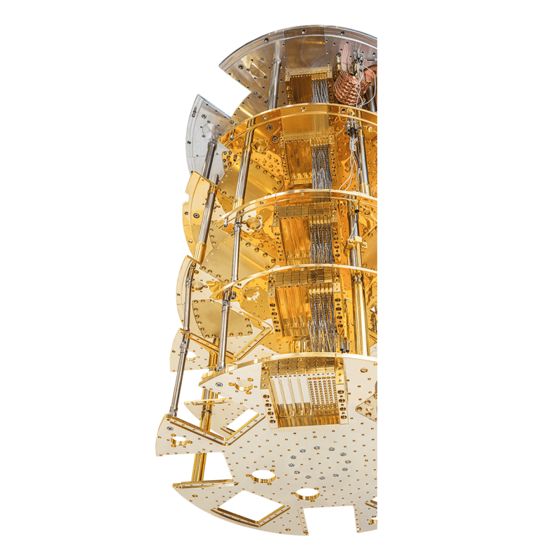
The XLDsl System features a variety of access ports between the Room Temperature and the Mixing Chamber Flanges, the primary ports being the six side-loading line-of-sight (LOS) ports for experimental wiring.

  • 6 x Side-loading ports (LOS)
  • 3 x KF40 (LOS)
  • 4x KF40

The side-loading system is compatible with our High-Density Wiring options. High-Density Wiring is a modular option for the XLDsl dilution refrigerator measurement system that enables high scalability for the experimental wiring, especially for high-frequency signals.

Read more about High-Density Wiring


Vast Experimental Space

Mixing Chamber Flange Diameter: 500 mm | 20″

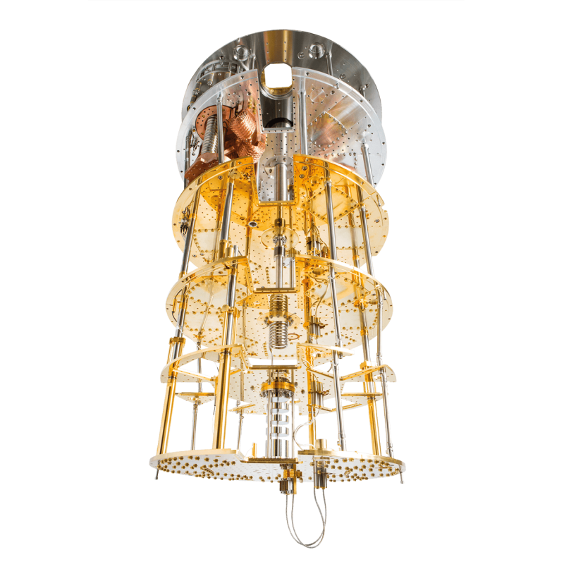
A centrally-placed unit distributes the cooling evenly around the Mixing Chamber Flange. The open design permits easy experiment access without the heat exchangers or system support structure obscuring access.


Superior Performance

  • Base temperature below 10 mK
  • Cooling power: >30 µW at 20 mK
  • Cooling power: >1000 µW at 100 mK

See all technical specifications


Temperature Controller

The Bluefors Temperature Controller enhances the user experience of our cryogenic systems. With a modern and intuitive user interface, you gain direct control and overview of the system’s temperature status.

The Bluefors Temperature Controller is fully integrated to all dilution refrigerator measurement systems.

Read more about the Temperature Controller


Low Total Cost of Ownership

Oil-free pumps and compressors in the Gas Handling System guarantee minimal maintenance requirements with a service interval up to 3 years. The systems contain only high-quality components such as Pfeiffer Vacuum pumps and pressure sensors, VAT vacuum valves and bellows.


Services

Total System Care

Total System Care enables you to focus on your own work – doing research and measurements. The service ensures that systems operate at the best possible performance level and with maximal uptime, without users needing to spend time maintaining the systems themselves.

Technical Specifications


2.0

XLDsl

Dilution Refrigerator Measurement System

Note: Cooling power is measured from experimental flange outside the Mixing Chamber. Cooldown time to base temperature is measured from an empty system with standard experimental space and shield set.

XLD1000slGuaranteedExpected
Base temperature 10 mK8 mK
Cooling power at 20 mK>30 μW34 μW
Cooling power at 100 mK>1000 μW1100 μW
Cooling power at 120 mK>1400 μW1600 μW
MXC Flange Diameter500 mm

XLD400sl GuaranteedExpected
Base temperature 10 mK8 mK
Cooling power at 20 mK>14 μW16 μW
Cooling power at 100 mK>400 μW450 μW
Cooling power at 120 mK>575 μW650 μW
MXC Flange Diameter500 mm

Pulse Tube Cryocooler Configurations


3.0

XLDsl

Dilution Refrigerator Measurement System

Cryomech Pulse Tube Cryocoolers with remote motors provide cryogenic cooling power to the dilution refrigerator measurement system without the need for liquid cryogens. The cooldown time of the system partly depends on the selected pulse tube power.

The standard XLD1000sl System is equipped with two PT420-RM pulse tubes. The pulse tube model can be upgraded to PT425-RM for increased cooling power at the 4K Flange.

XLD400sl is available with dual PT415-RM (default), PT420-RM, and PT425-RM configurations.

XLD1000sl is also available with triple PT420-RM, and PT425-RM configurations providing even more cooling power on the 4K Flange. Three pulse tubes reduce the number of side-loading ports to five. The XLD1000sl system can then be equipped with an additional 4K Flange.

New: PT310-RM configuration is now available. PT310-RM configuration provides 10% increase in MXC Flange cooling power. Learn more here.

Options


4.0

XLDsl

Dilution Refrigerator Measurement System

Note: XLDsl has configurations with two or three Pulse Tube Cryocoolers. The Additional 4K Flange option requires the third Pulse Tube Cryocooler integration. Still Heat Pipe is always included in XLDsl systems.

Performance Graphs


5.0

XLDsl

Dilution Refrigerator Measurement System

1Start cooldown
2Start pulse pre-cooling
3Stop pulse pre-cooling
4Start mixture condensation
5Stop mixture condensation
6Normal circulation mode

Figure above shows the cooldown curves for a configuration of an XLD1000sl System with dual PT420-RM pulse tubes, 625 mm sample space height, without Mixing Chamber Shield, 168 High-Density Wiring, and 25 coax lines to 4K Flange.

1Start cooldown
2Start pulse pre-cooling
3Stop pulse pre-cooling
4Start mixture condensation
5Stop mixture condensation
6Normal circulation mode.

Figure above shows the cooldown curves for a configuration of an XLD1000sl System with dual PT420-RM pulse tubes, 625 mm sample space height, with Mixing Chamber Shield, and minor wiring.

Pulse Pre-Cooling sequence is one of the key points in reducing the cooldown time (see spots 2 and 3). Because we do not use exchange gas some parts of the dilution refrigerator unit stay ‘hot’ on cooldown, which prevents condensation of the mixture. To cool down these hot spots effectively, the mixture is repeatedly admitted from the tanks to the Still side of the dilution refrigerator to operate as an exchange gas and then pumped out again.

1Start cooldown
2Start pulse pre-cooling
3Stop pulse pre-cooling
4Start mixture condensation
5Stop mixture condensation
6Normal circulation mode

Above are cooldown curves for two different configurations of XLD400sl systems measured with calibrated resistance thermometers.

  • System 1: basic XLD400sl with 75 coaxial lines and 144 DC lines.
  • System 2: XLD400sl with extra space, Mixing Chamber Shield, and additional sample mounting plate.

Pulse Pre-Cooling sequence is one of the key points in reducing the cooldown time (see spots 2 and 3). Because we do not use exchange gas some parts of the dilution refrigerator unit stay ‘hot’ on cooldown, which prevents condensation of the mixture. To cool down these hot spots effectively, the mixture is repeatedly admitted from the tanks to the Still side of the dilution refrigerator to operate as an exchange gas and then pumped out again.

Services

Customer Care

We support our customers throughout the lifetime of their system, providing dedicated care to find solutions for any issues. Our technicians and engineers are ready to help you wherever you are located, with prompt service delivered either remotely or on-site.

Related Products


Layout and Facility Requirements


6.0

XLDsl

Dilution Refrigerator Measurement System


Layout Overview

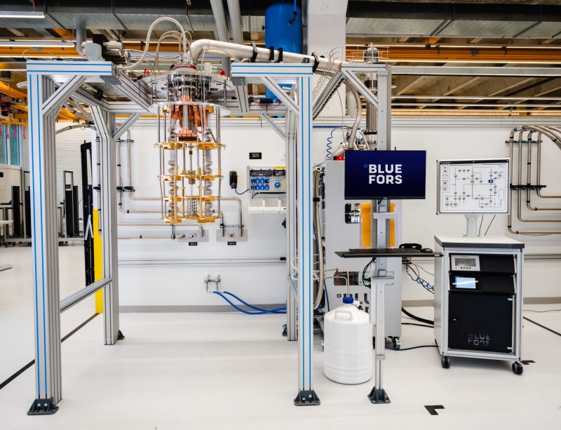
Bluefors XLD System layout overview.
1. Cryostat and its support frame, 2. Thermometry Unit, 3. Gas Handling System, 4. Pulse Tube Cryocooler compressors.

Each Bluefors system is designed to be installed to a specific location defined in advance. A separate layout drawing is made for each Bluefors system, which should always be referred to for exact dimensions.

Facility Requirements

The basic requirements are 3-phase electricity, cooling water, and compressed air. The full list of requirements and specification details can be found in the Pre-Installation Guide, please contact our sales team for a copy.

Get in touch with us.

Contact form – choose your product or service interest:


Name(Required)

Your personal data will be processed in accordance with our Privacy Notice.

This field is for validation purposes and should be left unchanged.
Name(Required)

Your personal data will be processed in accordance with our Privacy Notice.

This field is for validation purposes and should be left unchanged.
Name(Required)
Address

Your personal data will be processed in accordance with our Privacy Notice.

This field is for validation purposes and should be left unchanged.
Name(Required)
Address

Your personal data will be processed in accordance with our Privacy Notice.

This field is for validation purposes and should be left unchanged.
Name(Required)

Your personal data will be processed in accordance with our Privacy Notice.

This field is for validation purposes and should be left unchanged.
Name(Required)

Your personal data will be processed in accordance with our Privacy Notice.

This field is for validation purposes and should be left unchanged.