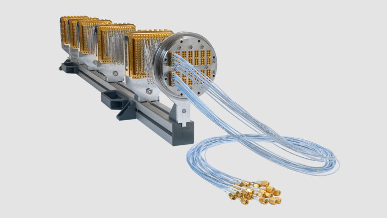
Skip to content

Coaxial Wiring

Measurement Infrastructure

Coaxial wiring combines excellent electrical and thermal properties for cryogenics, allowing our systems to remain below or close to 10 mK for all practical configurations of our factory-installed wiring.

Cryogenic experiments require special electrical and thermal properties such as low signal loss, EM shielding, and attenuation. In addition, minimal induced thermal load, proper thermal anchoring, and reliability are crucial qualities for successful experiments.

Our Coaxial Wiring options have been developed to meet these requirements, operating reliably in the cryogenic environment of our systems with repeated thermal cycling.

Great care has been taken to thermally anchor the coaxial assemblies to our systems and at the same time optimize both their electrical and thermal properties. These efforts allow our systems to remain below or close to 10 mK for all practical configurations of our factory-installed wiring.

All our assemblies are manufactured in-house and are fully tested before installation or shipping.

Product Highlights


1.0

Coaxial Wiring

Measurement Infrastructure


Wide Frequency Range Solutions

We offer a wide range of Coaxial Wiring solutions, from lossy Thermocoax wires with excellent high frequency filtering properties, to coaxial assemblies with high bandwidths. Our solutions range from 0 GHz all the way to 40 GHz.


Large Variety of Attenuators

Our coaxial wiring options include a large variety of possible attenuators with different attenuation values, properties, and materials.


Wiring Solutions Based on Experimental Needs

Wiring solutions include different options, such as multiple attenuators, additional breakouts, or additional cable length. With these options, our wiring solutions can be optimized based on your experimental needs.


Integrated Measurement Infrastructure

Along with Coaxial Wiring, we offer Measurement Infrastructure components that have been developed and tested to work optimally with our wiring. Solutions include filtering, diagnostics, and amplifier integration.


Services

Total System Care

Total System Care enables you to focus on your own work – doing research and measurements. The service ensures that systems operate at the best possible performance level and with maximal uptime, without users needing to spend time maintaining the systems themselves.

Semi-Rigid Coaxial Wires for High Frequencies


2.0

Coaxial Wiring

Measurement Infrastructure

For high-frequency measurements, we offer a wide variety of semi-rigid coaxial lines, thermalized at each thermal stage in the system by a combination of attenuators and F/F bulkhead feedthroughs mounted in our RF Installation Set (depending on material, coaxial lines can also be without attenuation at each stage).

The high frequency coax lines have two available connector types: SMA male and K/2.92 mm male with 18 GHz and 40 GHz maximum frequencies, respectively. Available cryo-attenuator values are: 0, 1, 3, 6, 10, 20, and 30 dB (all 2 W).

The bulkheads provide mechanical support and thermalize the outer conductor of the coaxial lines. Because the PTFE dielectric prevents a good thermal contact to the inner conductor, it is recommended to use attenuators directly screwed on the bulkheads to also thermalize the inner conductor.

Note: 2.19 mm cable is not recommended in large quantities due to the excessive heat load to 4K stage. It is mostly suitable for the low signal loss lines in combination with NbTi. Not available in high-density RF wiring.

Option 1: 2.19 mm SCuNi-CuNi
Characteristic impedance50 Ohm
Dielectric PTFE1.67 mm diameter
Center conductor CuNi (Ag-plated)0.51 mm diameter
Outer conductor CuNi 2.19 mm diameter
Attenuation (RT)1.2 dB/m @ 1.0 GHz, 3.8 dB/m @ 10.0 GHz
Attenuation (4K)0.6 dB/m @ 1.0 GHz, 1.8 dB/m @ 10.0 GHz
Thermal conductivity @ 4 K2.2E-4 W.cm/K
Option 2: 0.86 mm SCuNi-CuNi
Characteristic impedance50 Ohm
Dielectric PTFE0.66 mm diameter
Center conductor CuNi (Ag-plated)0.20 mm diameter
Outer conductor CuNi 0.86 mm diameter
Attenuation (RT)3.0 dB/m @ 1.0 GHz, 9.5 dB/m @ 10.0 GHz
Attenuation (4K)1.5 dB/m @ 1.0 GHz, 4.6 dB/m @ 10.0 GHz
Thermal conductivity @ 4 K7.1E-5 W.cm/K

Option 1: 0.86 mm SCuNi-CuNi
Characteristic impedance50 Ohm
Dielectric PTFE0.66 mm diameter
Center conductor CuNi (Ag-plated)0.20 mm diameter
Outer conductor CuNi 0.86 mm diameter
Attenuation (RT)3.0 dB/m @ 1.0 GHz, 9.5 dB/m @ 10.0 GHz
Attenuation (4K)1.5 dB/m @ 1.0 GHz, 4.6 dB/m @ 10.0 GHz
Thermal conductivity @ 4 K7.1E-5 W.cm/K
Option 2: 0.86 mm NbTi-NbTi
Characteristic impedance50 Ohm
Dielectric PTFE0.66 mm diameter
Center conductor CuNi (Ag-plated)0.20 mm diameter
Outer conductor CuNi ~0.86 mm diameter
Attenuation (RT)9.0 dB/m @ 1.0 GHz, 30.5 dB/m @ 10.0 GHz
Attenuation (4K)< 0.5 dB from DC up to 20.0 GHz
Thermal conductivity @ 4 K4.63E-6 W.cm/K

Dissipative and Low-Noise Coaxial Wiring


3.0

Coaxial Wiring

Measurement Infrastructure

At cryogenic temperatures, thermal contraction can make semi-rigid coaxial cables, especially Teflon-based ones, sensitive to vibrations. The vibrations can couple as electrical noise on the coaxial cables, creating so-called Triboelectric noise. To mitigate this noise, the charging effects from a moving dielectric need to be reduced. In flexible Grapho coaxial cables, this is achieved with a graphite-coated dielectric insulator. In addition to the graphite coating, these cables also have an FEP jacket around the outer conductor, which shrinks during cooldown and effectively reduces the movement of the coaxial conductors/insulators.

Our flexible coaxial wire assemblies work well up to a few GHz. The assemblies are thermalized at each thermal stage in the system by a combination of attenuators and F/F bulkhead feedthroughs mounted in our RF installation set. The wires come with SMA male connectors.

Note: Requires RF installation set.

Parameters
Characteristic impedance50 Ohm
Dielectric PTFE0.66 mm, graphite-coated
Center conductor CuNi (Ag-plated)0.20 mm diameter
Outer conductor CuNiFlexible braid, 90% shielding
InsulationFEP jacket around outer conductor
Attenuation (RT)5.4 dB/m @ 1.0 GHz
Attenuation (4K)4.3 dB/m @ 1.0 GHz

Thermocoax


4.0

Coaxial Wiring

Measurement Infrastructure

For high-frequency filtering, we offer sets of 6 Thermocoax lines from room temperature to the MXC. As the high frequencies are filtered out, these lines offer coaxial geometry for DC and low frequency measurements. Thermocoax lines are 3 m long and are anchored with gold-plated copper bobbins to DC Installation Set Flanges at every temperature stage. An optional breakout at the 4K stage is available for these wires.

At room temperature, these lines terminate in a Feedthrough Box with SMA connectors. The Feedthrough Box uses a KF40 port and can fit up to 24 Thermocoax lines. However, as the DC Installation Set can take maximum of 4 x 12 Thermocoax lines, it is possible to use two breakout boxes with 24-line feedthroughs and route all the 48 lines to one KF40 LOS port (below the RT stage) to preserve the LOS ports in the system. The low-temperature breakout terminal can be fitted with SMA connectors.

Note: Requires DC installation set.

Length [m]Diameter [mm]Resistance [Ω]Capacitance [pF]
Thermocoax Nc Ac RT-MXC3 ± 5%0.5 ± 5%155 ± 5%562 ± 5%
Thermocoax Nc Ac RT-4K1.9 ± 5%0.5 ± 5%100 ± 5%356 ± 5%
Thermocoax Nc Ac 4K-MXC1.5 ± 5%0.5 ± 5%80 ± 5%281 ± 5%

Continuous CuNi-CuNi Coaxial Wire


5.0

Coaxial Wiring

Measurement Infrastructure

For DC and low frequency measurements in coaxial geometry, we offer continuous CuNi-CuNi lines in sets of six 0.86 mm lines. Continuous CuNi lines are anchored with gold-plated copper bobbins to DC Installation Set flanges at every temperature stage. The continuous CuNi lines are not as resistive as Thermocoax and offer a higher cut-off frequency compared to Thermocoax. Because of the tight loops inside the thermalization bobbins, the frequency regime is lower compared to normal high-frequency SCuNi-Cuni lines. Continuous CuNi lines work well up to 5 GHz.

At room temperature, continuous CuNi lines terminate in a breakout box with SMA connectors. The breakout box uses a KF40 port and can fit up to 24 continuous CuNi lines that can be fitted to one DC Installation Set. The low temperature breakout terminal uses SMA connectors. Additional breakouts in different temperature stages can be installed according to customer needs.

Note: Requires DC installation set.

Services

Customer Care

We support our customers throughout the lifetime of their system, providing dedicated care to find solutions for any issues. Our technicians and engineers are ready to help you wherever you are located, with prompt service delivered either remotely or on-site.

Related Products


Installation sets


6.0

Coaxial Wiring

Measurement Infrastructure

The gold-plated copper bobbins are mounted on a DC Installation Set for a proper thermalization. The DC Installation Set includes a hermetic feedthrough connector box at room temperature and one aluminium and four gold-plated copper thermal anchoring feedthrough flanges for the 50K, 4K, Still, Cold Plate, and Mixing Chamber stages.

Number of DC Installation Set feedthroughs for each port size:

Port sizeKF25KF40KF63XLDsl
Feedthroughs1, 3, or 43 or 4109

The standard port for the DC Installation Set is KF40, which can have a maximum of four feedthroughs. This means a maximum of 4 x 12 TWP (total of 96) DC wires per KF40 port.

The proper thermal anchoring of coax lines is critical for cryogenic experiments. In a Bluefors RF Installation Set, the coaxial lines are thermalized at each stage by Female/Female (F/F) bulkhead feedthroughs. On each stage, these bulkheads are mounted onto thermalization flanges. The RF installation set includes a hermetic feedthrough at room temperature. These RF Installation Sets are purchased as separate items without coaxial cables and attenuators.

Available RF Installation Set feedthroughs for each port:

Port Size (LOS)Port: number of holes for RF feedthroughs
KF25
SMA (18 GHz) or K 2.92 mm (40 GHz)
1
KF40
SMA (18 GHz) or K 2.92 mm (40 GHz)
4/6/7
KF63
SMA (18 GHz) or K 2.92 mm (40 GHz)
8/12/16/20/21
ISO-100 (side-loader)
SMA (18 GHz) or K 2.92 mm (40 GHz)
25/32

Technical Requirements


7.0

Coaxial Wiring

Measurement Infrastructure

Note: Thermocoax and Continuos CuNi-CuNi coaxial assemblies are installed into the KF40 ports with a DC installation set. Flexible Grapho and semi-rigid coaxial assemblies require RF installation sets.

SD

Free KF25 port or KF40 port for installation.

LD

Free KF40 port or KF63 port for installation.

XLDsl

Free KF40 port or side-loading port for installation

Get in touch with us.

Contact form – choose your product or service interest:


Name(Required)

Your personal data will be processed in accordance with our Privacy Notice.

This field is for validation purposes and should be left unchanged.
Name(Required)

Your personal data will be processed in accordance with our Privacy Notice.

This field is for validation purposes and should be left unchanged.
Name(Required)
Address

Your personal data will be processed in accordance with our Privacy Notice.

This field is for validation purposes and should be left unchanged.
Name(Required)
Address

Your personal data will be processed in accordance with our Privacy Notice.

This field is for validation purposes and should be left unchanged.
Name(Required)

Your personal data will be processed in accordance with our Privacy Notice.

This field is for validation purposes and should be left unchanged.
Name(Required)

Your personal data will be processed in accordance with our Privacy Notice.

This field is for validation purposes and should be left unchanged.